Why water still moves after the pump stops
Two different mechanisms look identical at the end of the tube:
- Electrically driven pumping. The pump still has power, or the control that was supposed to remove it did not.
- Gravity flow through a flooded line. The tube stays liquid-filled and connects a higher free water surface to a lower free surface, or to a lower free outlet, so it keeps moving water with the pump unpowered.
A level sensor, float switch or maximum-runtime limit is a pump control. None of them admits air into the tubing, so none of them breaks a continuous water column. That is why the first distinction to make is pump control versus plumbing, and why a supervised pump-off check is useful: it separates a pump that is still running from a line that can still drain. It provides evidence about the mechanism at that moment, not a single definitive cause.
Which direction the water is moving
Both siphons need a continuous liquid path. They differ in which end is the source, and that changes what you check.
Forward siphon: reservoir to tank or sump
This is the usual pattern after a top-off pump stops. The reservoir's water surface is higher than the discharge point, the intake stays submerged in the reservoir, and the tube remains full. When the discharge is freely into air, compare the reservoir's free water surface with the free outlet: that difference is the driving head, and the pump adds nothing once the column is established. A line that has drained, with air trapped at a high point, will not restart on its own.
Both ends do not need to be submerged. A tube discharging freely into air will still siphon while its reservoir end stays under water, so an outlet held above the receiving tank's water line—a physical air gap—does not stop forward flow from a reservoir whose surface is above that outlet. The air gap protects against water from the tank running backward; it cannot cancel head that comes from the reservoir side.
Forward flow stops when the reservoir surface drops to the level of the discharge opening (or below the intake), when the intake draws air, or when air reaches the line at a point above the reservoir surface. With a free outlet, that stopping point is set by the reservoir and the outlet, so it need not mean the reservoir and the receiving tank end up at the same level.
Reverse siphon: tank or sump to reservoir
With both ends of the line submerged—a top-off outlet below the water line in a sump or display, and the reservoir end under water—the driving head is the difference between the two free water surfaces, not the depth of the reservoir's submerged pump, intake or tube end. Reverse flow needs the tank or sump surface to stand higher than the reservoir's free surface, a continuous water-filled route between the two submerged ends, and nothing along that route admitting air.
A submerged tank end and a route that passes to a lower point are not enough on their own. If the receiving reservoir's free surface is higher than the tank's, the head points the other way: the line runs from the reservoir toward the tank, not backward. The tank drains toward the reservoir only while its free surface stays above the reservoir's, and the flow stops when the surfaces equalize or the tank end draws air.
If the tank end sits above the water, reverse flow has no submerged path to start from, and air can enter the line there. That is the direction an outlet air gap actually protects. An outlet above the water line is therefore not a complete anti-siphon setup on its own.
A contained pump-off check
Not every trickle after the pump stops is a live siphon. The tube holds water of its own, and any segment above the water line drains until the column breaks. That is a brief line drain-down or residual flow: it is limited to the line's contents and slows or stops as the line empties.
Sustained unwanted flow behaves differently. The reservoir level keeps falling, and the flow holds its rate past the point where the line's own volume should have run out.
To check which one you have:
- Keep the outlet and the receiving vessel in view, and catch any overflow so water stays off electrical equipment.
- Note the reservoir and tank levels first, so you can tell whether either moves during the test.
- Disconnect the pump at a dry point—unplug it or switch off its feed—so it cannot run electrically. Stay with the system while it is unpowered.
- Watch the outlet long enough to see whether the flow fades with the line's contents or keeps running.
- Keep the pump unpowered until any unintended flow is contained and the tubing route is safe.
How to read the result:
- The flow fades and stops with the line's contents. That is consistent with drain-down. Check for a control that kept running or a slow leak, and repeat the check at a different reservoir level.
- The flow keeps running with the pump unpowered. Gravity has a path. Compare the two free water surfaces if both ends are submerged, or the reservoir surface with the free outlet if the discharge is in air, then check submersion and any maker-supplied siphon break.
- The flow stops during this check. That is one observation at one reservoir level. Raising the reservoir can restore forward head, and a rising tank level can start reverse flow, so a single pass does not rule out a siphon.
What a supplied siphon break can and cannot do
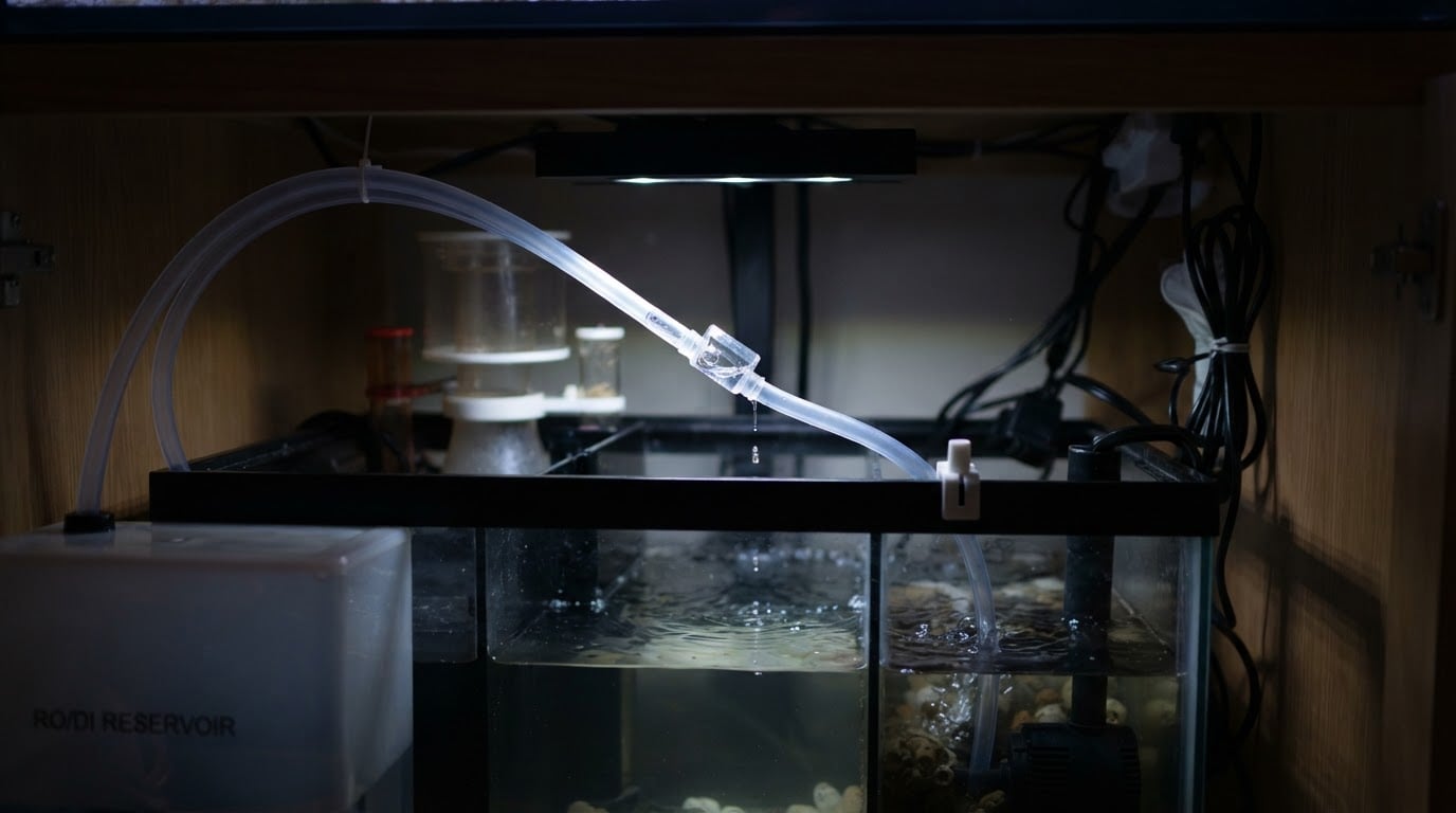
The current ReefBreeders ATO includes a siphon break, listed as preventing back-siphoning. The maker says the fitting lets air into the line when the pump is off, which stops unwanted siphoning, and that it can also release a small amount of water, so it should always be positioned inside the rim of the aquarium, sump or ATO reservoir.
Those are two different requirements. Positioning inside the rim controls where the discharge lands. The height and orientation that let the fitting admit air come from the manual for your unit—a position that merely sits inside a vessel rim is not by itself a safe air-break position. A simple open air vent admits air only while its opening sits above the water level driving the flow; below that level, water can escape through it instead. A proprietary siphon break need not follow that plain-vent rule—this fitting is described as admitting air when the pump is off—so use its maker's orientation and height rather than a universal air-admission height applied to every design.
Treat the fitting as part of the route, not as a second controller:
- Expect a little discharge there, and place it where that stays inside a vessel.
- Follow the maker's height and orientation for your model rather than a generic rule.
- Secure the outlet in its holder so it cannot slide deeper or fall into a lower path.
- If your kit has no siphon break, routing and outlet height still matter; you simply do not have that fitting to place.
An added check valve is not a substitute for a correct route. It adds a part that can stick or leak, so do not rely on it as the only fix. Do not drill tank walls, lids or equipment for an air hole unless the manufacturer's instructions call for that step.
Route the line with both water surfaces in mind
Walk the tubing from the reservoir to the outlet. Identify which condition applies, then compare the right pair: the reservoir's free surface against a free outlet, or the two free surfaces when both ends are submerged.
Check | What keeps unwanted flow from starting | What still allows it |
|---|---|---|
Free outlet (discharge into air) | Outlet at or above the reservoir's free water surface, leaving no forward head | Reservoir free surface standing above the free outlet |
Both ends submerged | Receiving reservoir's free water surface at or above the tank's free surface, so there is no head toward the reservoir; the tank end above the normal water line is a second guard | Tank's free surface above the reservoir's free surface, with a continuous submerged path and no air admitted |
Air break | A simple open vent above the water level driving the flow, or a proprietary fitting set to its maker's orientation and height | A vent below the driving water level, or a proprietary fitting installed outside its maker's specification |
Outlet fixing | Outlet held above the intended level and unable to slide or fall | Loose end that can drop underwater or into a lower route |
Pump control | Sensor and runtime limit stop the pump, with the line checked separately | Treating "pump off" as proof that the line cannot flow |
Evaporation, top-off volume and the route
Evaporation sets how much fresh water the system needs and how often the pump runs; measuring your reef tank's evaporation rate gives you a volume to size the reservoir around. Siphoning is a separate question—where that water can go when the pump is not running. A pump that sticks on can overfill and dilute salinity, and one that sticks off lets salinity climb, so both the volume and the route deserve a look.
If flow continues after the outlet is secured and the break is positioned as the manual specifies, keep the pump unpowered, contain the water, and re-check the outlet and break heights against the reservoir surface before touching the controller. Then move to sensor placement, calibration and runtime limits with the same supervised method. Keep the disconnection dry and the electrical side out of the water.